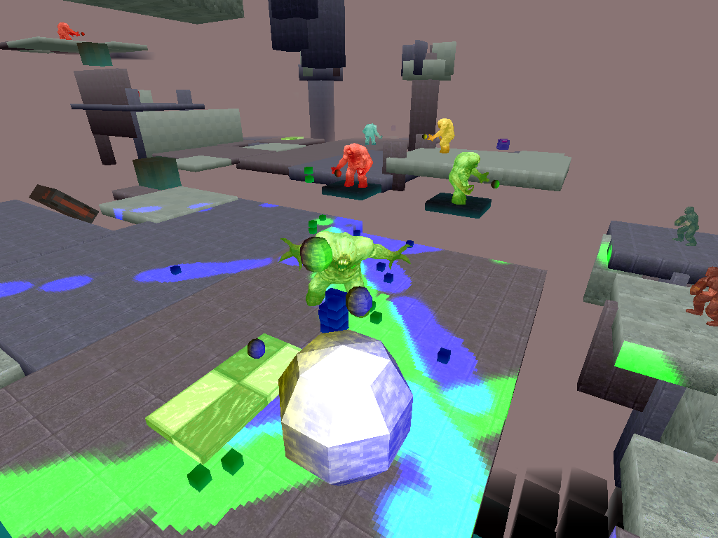
 Read about the front end of the renderer here.
The front end or geometry stage of the renderer finishes with all valid scene triangles having their screen space coordinates written to the buffers of the screen bins they cover, where a valid triangle is one that is front facing, has pixel coverage and lies within the view volume,
The back end of the renderer has a series of distinct stages:
- Visibility buffer fill
- Visible triangle atrribute fetch and shading
- Visible fragment pixel shading
Visibility Buffer Fill
Triangles are fetched from the bin buffer and rasterised into a stream of raster fragments. For more details on this see the post on the rasteriser.
Those fragments that survive the depth test write into a visibility buffer, analogous to the other screen buffers such as depth and colour, except into this buffer we write a 32-bit value that uniquely identifies the triangle, and maps back into the triangle’s bin entry, which in turn indexes the parent triangle’s vertex data. Once all the bin triangles have been processed this buffer contains the id’s of all and only the visible triangles in the frame.
Visible Triangle Attribute Fetch & Shading
The visibility buffer is parsed a row at a time, leveraging spatial coherence by writing out edge pixels, removing duplicates, and checking against existing ID’s stored in a hash table. The output of this process is a list of visible triangles grouped according to draw call.
The list is stepped through and for each triangle attributes are fetched and shaded. Attribute shading consists of multiplying by an attribute matrix, or applying some basic vertex lighting. Attribute deltas are computed for barycentric interpolation in the shader. The rasteriser is re-run for each triangle, but this time instead of using the depth buffer as a write mask, the visibility buffer is used. The raster fragments are fed into the pixel shader.
Pixel shading
Lamorna engine’s pixel shading is fairly simple in it’s scope. It can perform perspective correct 3-channel colour interpolation and perspective correct point sampled texture mapping with per fragment mip-mapping, where in my parlance a fragment is a 4×4 pixel block, with either clamp or wrap.
The shading process proceeds a fragment at a time, and opens by stepping the edge values emitted from the rasteriser to the pixel centres, and multiplying through by the inverse of the triangle area to yield the normalised screen space barycentrics. These barycentrics are used to step 1/z depth across the fragment. A second set of barycentric coordinates now come into play. These barycentric coordinates were assigned in the front end and underwent clipping, projection and binning along with the position coordinates. Interpolating these across the fragment and dividing by the depth yields barycentric coordinates for the current pixel in the original clip-space triangle, which allows us to interpolate un-clipped and un-projected vertex attributes from that point on in the shader.
Once all the visible triangles have been shaded the bin colour buffer contains the final output of that bin for the frame.
While the whole screen is divided conceptually into 128×128 pixel bins, there are in reality only as many bin buffers as there are worker threads. When a thread has finished processing the contents of a bin, the bin colour buffer is written down to the DirectX surface buffer.
Each 64×64 tile within the screen bin is mapped using morton coding to improve memory access patterns, so the colour buffer is swizzled during copy down. All buffers are cleared ready for the next bin.
Considerations:
- The visibility buffer complicates the rendering process but is intended to remove the effects of overdraw in the pixel shaders. It allows attribute fetch, shading and pixel shading to be wholly limited to visible triangles.
- The hi-jinks with the two barycentric types is in part necessitated by the deferred pipeline. Attributes need to be either clipped explicitly after fetching which would be messy, or implicitly via the clipped barycentrics.
- The shaders make heavy use of SIMD, processing 4 elements at a time. The lack of a feature complete vector ISA hurts here, as things like texture reads and computing mip-map levels must be done using scalar code.
- I find it necessary to clamp u & v values in the shader to prevent the occasional bogus texture read.
- Draw calls are used to group models having similar pixel shading routines.
- I have in the past implemented tri and bi-linear filtering, and texture blending, but they led to unacceptable performance degredation.
